Infrared Optics FAQs

Below you’ll find answers to the questions we get asked the most when looking for a required IR optics solution.

Reduced SWaP Continuous Zoom Lens for MWIR 10 μm pitch VGA Sensors

A: LightIR 16-180 mm f/3.6 continuous zoom lens is a compact, folded design that reduces size while maintaining a long effective focal length (EFL). It uses fewer optical elements than similar focal length lenses to reduce weight. It is designed with low power consumption to meet design criteria.

A: Almost any application can benefit from reducing size, weight, and power, but in some applications it is essential. Drone and UAV designers are constantly balancing the size and lift capacity of the aerial vehicles with the sophisticated technology needed in the payloads. The Ophir LightIR 16-180 mm f/3.6 lens allows for a sophisticated, long-range MWIR sensor while limiting the payload size, weight and power consumption. This makes it ideal for airborne gimbles on SWaP constrained platforms. It is specifically designed to enhance imagery in MWIR 640x512 10 µm pitch sensors preferred by engineers with SWaP constraints.

A: Even though SWaP constraints limit size, weight and power, the performance required of the systems cannot be compromised. Imaging systems must maintain the ability to produce clear, crisp images for the end user. Ophir’s LightIR 16-180 mm f/3.6 lens maintains excellent MTF (modulation transfer function) as well as maintaining focus throughout the zoom. It also includes fast zoom and focus, tight boresight, low power consumption, wide operational temperature range, and high durability in harsh environmental conditions. Ophir has created a unique design that implements strict quality control to achieve the best images any given sensor can produce.

A: Maintaining high performance in any lens begins in the design phase, the key to the designs is to build in performance and manufacturability. Near diffraction limit MTF with a design that allows for some minor tolerances in the build cycle leads to a superior product that meets or exceeds its testing requirements. Ophir’s state-of-the-art manufacturing facilities maintain tight quality control over the entire manufacturing process from design to delivery, to ensure a superlative product.

A: Single- and dual-FOV (field of view) lenses are not well suited to SWaP constraints. Single FOV does not provide the flexibility required by systems engineers and dual-FOV cannot meet size and weight constraints. Ophir’s LightIR 16-180 mm f/3.6 lens provides a wide FOV for detection and situational awareness and continuously narrowing FOV for identification of objects of interest. The folded optical design allows this in a smaller volume package perfect for SWaP design constraints. In order to withstand harsh environmental conditions, the lens is offered with high durability (HD) and low reflection hard carbon (LRHC) AR coatings.

A: Drone and UAV design engineers are perpetually balancing size and capability requirements for each aerial system. Larger aerial vehicles have larger lift capacities, but cannot be readily moved by the people who operate them. Smaller aerial vehicles have limited range and limited lift capability. In order to balance these constraints, design engineers detail size, weight and power requirements for each subsystem used on a particular design. Ophir works with sensor manufacturers as well as drone and UAV designers to provide the best optics to meet these rigorous needs. LightIR 16-180 mm f/3.6 is the culmination of this teamwork between optics designers and the end users of complex aerial systems.

A: When it comes to developing optical components and optical systems for UAV payloads, three factors must be measured. These factors can be summarized by the acronym SWaP – size, weight, and power consumption. UAV payloads, especially for smaller commercial UAVs, impose strict size and weight restrictions. Power consumption must be reduced to minimize fuel usage, thus maximizing flight time.

The optical payloads for small autonomous aerial systems must be able to provide high optical performance despite their compact form. Detectors are increasing in both resolution (number of pixels) and format (size), while decreasing in pixel size, which puts pressure on optical manufacturers to make smaller, lighter optics with lens quality that will still allow for maximum imaging performance.

Various technologies are being used to meet these optical needs. These technological solutions include innovative optical and mechanical designs, free-form optics, and unique lens coatings.

Large mirrors for multispectral optical systems

A: Over the last 10 years, multi-spectral optical systems have been used by system integrators in the defense and aerospace industries, in surveillance and monitoring, and in certain commercial applications. Multi-spectral optics enable many new possibilities for defense and national security missions on land and sea. Multi-spectral imaging systems enable the combining of multiple cameras into one, to significantly improve performance without increasing size and weight. These systems generally have long focal length and are meant for long-distance surveillance, possibly tens of kilometers. The multi-spectral optics enable maximum error correction and allow for a wider field of view, performing to a high level across a wide range of wavelengths (Short-wave IR, Mid-wave IR, Long-wave IR, Visible and Near IR). They allow for high day/night performance in situations where vision is obscured, such as low lighting and adverse weather conditions.

For example, multi-spectral optics is integrated into the optical systems of large unmanned aerial vehicles (UAVs) for the long-distance aerial monitoring of agricultural field temperature using IR, as well as in the aerospace industry, for satellites and long-range telescopes.

A: A multispectral electro-optical system (EOS) combines multiple optical channels into one, allowing significantly improved performance while reducing size and weight – all thanks to the inclusion of large mirrors. An electro-optical day/night system built for aircraft payloads providing high performance in harsh weather conditions is a perfect example of a multispectral EOS.

A: Long range defence, surveillance and monitoring applications use multi-spectral optical systems. Certain commercial applications also use a multi-spectral EOS. For example, aircraft or large UAVs often carry a multi-spectral EOS with an integrated large mirror in the payload.

A: Unlike lenses that are often bandwidth limited, large mirrors combine several imaging bands in the visible, NIR, SWIR, MWIR, and LWIR, allowing significantly improved performance without increasing the size and weight of the EOS. Large mirrors perform to a high level across a wide range of wavelengths including laser-based applications such as laser range finders (LRF) and laser designators.

The mirror’s reflection angles are identical for all wavelengths and, therefore, all optical channels can be combined, creating the multispectral system.

The mirrors are also the key enabler for a folded optics design contributing to reducing the size of the multispectral system.

Large mirrors play an important role in long-range reflective systems, for long distance surveillance, such as reflective telescopes. These telescopes use a combination refractive and reflective optics to maximize error correction and allow for a wider field of view.

Furthermore, Large mirrors are often integrated in the optical systems of defense and surveillance systems, for example, in large aircraft. These mirrors allow for the production of high resolution imagery during long distance surveillance and monitoring. To produce high quality images from a distance, the mirrors must meet a strict set of requirements. Detectors are increasing in resolution all the time, necessitating mirrors with increasingly accurate surfaces, meeting tight tolerances in terms of shape and irregularities. The multi-spectral nature of the optical systems means that mirrors must also be able to perform throughout a variety of wavelengths. They must have minimum roughness, especially when they are used in VIS wavelength, under 40Å rms (root mean square), to prevent light from scattering.

The Narcissus Effect

A:With its name taken from Greek mythology, narcissus is one of the unwanted effects of thermal imaging, whereby a cold detector images the reflection of itself and displays it in the processed video output. Whenever the thermal detector senses variations in background radiation caused by reflections from lens surfaces, the phenomenon of narcissus may occur.

A: Typically, the narcissus effect comes from the detector cold shield. The cold shield is kept at cryogenic temperatures, while the lens’ temperature is usually near ambient temperature. Narcissus occurs when the image of the cold shield is reflected from a surface in the lens train and is focused onto the detector. In such cases, the image of the cold shield shows in the middle of the display as a dark or bright circle. Because of the difference in temperature between the cold shield and the lens assembly, every infrared zoom lens in a system with a cooled detector is prone to narcissus.

A: To test levels of narcissus when manufacturing a lens system, Ophir sets up a narcissus simulation. Every surface of the lens system is examined through the entire zoom sequence, at many intervals. If the narcissus effect occurs at any point, it is measured, analyzed, and methods are put into place to correct it.

A: Narcissus reduction should be addressed during the manufacturing of a lens system. Here at Ophir, this is done through unique lens designs and anti-narcissus coatings that will prevent the production of back reflections that could focus on the detector and cause the narcissus effect.

Thermal Imaging

A: It's a tradeoff. Where customer’s requirements are for long range vision, high-sensitivity, a better signal to noise ratio, and atmospheric transmission – MWIR is the logical selection. The MWIR detector is more sensitive at a higher signal to noise ratio, and comes with a cooling mechanism, which makes it larger, and more costly. In other cases, when considering size, costs, and environmental harsh conditions (dust, smoke, sand, extreme temperatures), the LWIR is more appropriate.

Ophir’s MWIR lenses come with long Focal Length which makes them more suitable for longer range application. This is reflected in our product’s DRI capabilities with over 25 km, thanks to the very long EFL (around 1,000 mm or more). In comparison, Ophir’s LWIR DRI performance reaches approximately 13 km. The following is a comparison table that captures the main differences between MWIR and LWIR optical performance:

MWIR 3-5 µm wavelength LWIR 8-12 µm wavelength
Daytime vs Nighttime observation Lower performance Good performance, as the sun emits low radiation in this spectral range, and therefore there is less spectral noise
Smoke screen Lower performance Good performance
Dust screen Lower performance Good performance, as the LWIR long wavelength is less disrupted by small dust particles
Haze Lower performance Good performance
Humidity Good performance Lower performance due to high water absorption at this wavelength
Temperature sensitivity High Low
High signal sensitivity to noise ratio High Low
Wide landscape picture Lower performance Good performance, since landscape objects emit more radiation at a long wavelength
Matrix implementation Easier None
Long Range vision Good performance Lower performance
Cost and size High due to cooling system needed Low

Zoom lenses

A: Ophir addresses boresight retention using tight tolerances for all optical and mechanical elements, as well as backlash-free design. Using Ophir’s zoom lenses, once the zoom position is changed, the boresight is maintained, meaning that no adjustments are needed during optical system operation. This is an integral feature in zoom lens design, which we consider as part of the standard requirements and quality tests.

A: Ophir’s boresight error ranges from 0.15 mm to 0.35 mm at the focal plane.

Long Range Zoom Lenses

A: The focal length determines the field of view (FOV) of the thermal imaging camera. The longer the focal length, the smaller the FOV, which translates into more pixels across a target at a fixed range (meaning, the target angle divided by the IFOV angle).

For example, consider a man at a range of 1 km. The effective angle of the target is about 1 mRad (1 m/1000 m). If we consider, for example, a 500 mm focal length combined with a 15 μm pixel detector, the IFOV would be 30 μRad. Therefore, the number of pixels on a target is equal to the target angle divided by the aIFOV angle, which is about 30 pixels on the target 1000/30 (>8 pixels required for identification based on the Johnson’s criteria).

A: Extenders allow flexibility. A lens can be replaced easily, using the same basic lens body, with no need for hardware or software modifications. This lowers the complexity in the design and can also result in reduced NRE costs. Yet, reduced cost is not always achieved. Size and weight are mostly a disadvantage, as a second optical assembly is added to an existing one.

A: Most of Ophir’s lenses cover a wide range of temperatures, from -30°/40°C to 70°c, and even 85°c. Using proper coating and sealing techniques, the lenses are also resistant to high humidity. Dust and vibration are also environmental factors that are tested, to ensure resistance to harsh environmental conditions. Thanks to these features, Ophir’s lenses answer a wide range of application demands. In commercial applications, such as UAVs and drones, vibration management is crucial, as is the temperature range. Ophir’s key competitive advantage in IR zoom lenses is the ability to maintain a high level of optical performance, which is, for example, characterized by the modulation transfer function (MTF) throughout the temperature range, and in different environmental conditions. Ophir’s lenses provide outstanding performance, and an MTF close to the diffraction limit, over the entire temperature range, which is a critical demand for many applications.

Meeting Naval and Maritime Applications EO System’s Challenges

A: The maritime environment is certainly the harshest for any electro-optic system. Salt water and high wind combined with increased vibration and shock require extreme durability and the highest level of environmental sealing. Ophir meets this challenge with its high-durability (hard carbon) lens coatings, proven lens element sealing, and ruggedized optics.

A: Ophir’s lenses give ships an advantage by providing:

  • Crisp, focused images across the full zoom range
  • An MTF close to the diffraction limit to maximize detection, recognition, and identification (DRI) of targets for any given focal length
  • Fast zoom and focus provide mission critical imagery quickly and accurately
  • Shock, vibration, and the salt spray environment are the ultimate challenges to any optics manufacturer. Ophir has met those challenges with an engineering design team that created hard coatings, ruggedized optics and shock and vibration tested long-range lenses which enable unprecedent MTBF.

A: Missile ordnance with infrared imaging seekers is a unique challenge. Naval Strike missiles and Surface-to-air missiles have different physical requirements. NSMs are typically larger than their SAM cousins, but both optical designs need to meet the requirements of high-speed heat load and typically long storage times. Ophir offers customized optical components such as domes, mirrors and Cassegrain telescopes, which are essential to the effectiveness of guided missiles, making it possible to acquire and track ground and air targets (NSM and SAM), enable missile guidance detection and recognition, supporting robust imaging detecting systems.

A: Long-wave infrared is attenuated by moisture in the atmosphere much more than mid-wave infrared. Because of the high moisture content in the maritime environment, navies prefer MWIR for long-range surveillance missions. LWIR is typically used for shorter range missions and is commonly found in handheld and some weapon-mounted systems.

A: Ophir designed and developed continuous zoom technology with unparalleled concentricity and quick zoom movement. The ability to maintain focus across the full zoom range allows operators to keep situational awareness during FOV changes. Some other lenses in the defense market use two- or three-FOV systems that require refocus after an FOV change.

Optical Components

A: Ophir have free-form capabilities, as part of components manufacture. These include highly complicated unique components, such as mirrors and lenses designed to answer customers’ requirements.

Optical Coatings

A: Optical coatings typically consist of thin films made up of single or multiple layers of either metallic or dielectric materials. When properly designed and fabricated, these coatings can dramatically modify the reflection and transmission properties of an optical component. The properties can be controlled from the deep UV to the IR with narrowband, broadband, or multi-band response, and can be polarization sensitive. Optical coatings can be applied directly to the surface of an optical component to tailor its reflectivity, as in the case of an optical mirror or beam splitter. For other components, such as lenses, the applied coatings may simply improve their overall transmission properties by reducing surface reflectivity. When optical coatings are integrated into a monolithic component for the express purpose of controlling the spectral transmission of light, the component is referred to as an optical filter.

Ophir® Optics Optical Coating Capabilities

*Content credit: MKS Instruments Handbook: Principals and Applications in Photonics Technologies, by the office of the CTO. 1/2019. https://www.mks.com/mks-handbook

A: The individual layers that make up optical coatings are typically a few tens of nanometers to a few hundred nanometers in thickness, while a single optical coating can be comprised of several hundred layers. Consequently, the techniques used to deposit these layers require a high degree of precision. Generally, the process begins with surface fabrication to minimize surface roughness and sub-surface damage. It continues with surface cleaning and preparation and is followed by deposition of high-performance thin film designs. The deposition technologies include thermal evaporation, electron-beam, ion-assisted deposition, and advanced plasma deposition. The most appropriate coating technology for the intended product design depends on the operating environment, spectral requirements, physical characteristics, application requirements, and economic targets. The optical coating process is completed with comprehensive performance testing using sophisticated metrology tools.

Metal coatings used on optical mirrors typically consist of a single layer approximately 100 nm thick. This ensures that the broadband high reflectivity properties of the metal due to the complex index of refraction are present. In order to provide greater tuning of the reflectivity and over specific wavelengths of interest, dielectric coatings are used . These coatings consist of alternating high refractive index (nH = 1.8 – 4.0) and low refractive index (nL = 1.3 – 1.7)

dielectric layers (see Figure 3). The thickness of each layer is chosen such that the product of the thickness and the index of refraction of the layer is λ/4.


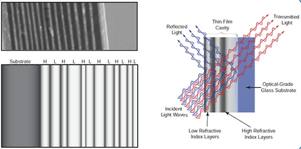
Figure 4. Scanning electron microscope image (top) and schematic (bottom) of an optical interference coating shown on left. Reflection and transmission of light by a filter consisting of an interference coating (right).

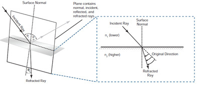
Dielectric optical coatings are used in a myriad of ways. In addition to highly reflective dielectric mirrors (see Figure 3), these coatings are incorporated in broadband beam splitters and IR wavelength lenses. When light is incident at an angle to a surface, i.e., not normal incidence, the reflectivity becomes polarization sensitive. This allows dielectric coatings to be polarization selective and such coatings are used in polarizing beam splitters (see Section III.A.5). In addition to enhancing the reflectivity, dielectric optical coatings can also be used to reduce surface reflections in the form of broadband anti-reflection coatings. These coatings can be applied to any optical component, e.g., lens, prism, beam splitter, window, to markedly improve its transmission efficiency. The reflection from an air-glass (n2 ≈ 1.5) interface gives a reflectivity of 4%, which can be reduced considerably with a broadband anti-reflection coating (see Figure 5).


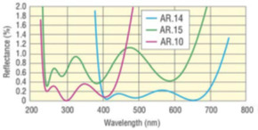
Figure 5. Typical broadband anti-reflection coating in the UV and VIS spectral regions.

These reflectivities can be reduced even more to improve transmission in laser systems with multiple optical elements, saving valuable laser energy from being lost to surface reflections. This superior performance, however, is achieved at the cost of reduced wavelength range.

Ophir® Optics Optical Coating Capabilities

*Content credit: MKS Instruments Handbook: Principals and Applications in Photonics Technologies, by the office of the CTO. 1/2019. https://www.mks.com/mks-handbook

Optical Lenses

A: Image quality is affected by all system components – lens, detector, electronics, image processing, and monitor.

The lens related image quality factors are:

  1. Diffraction limit
  2. Lens design
  3. Manufacturing tolerances

Diffraction limit is a physical limit, which depends on the wavelength and F# only, not on the lens design or manufacturing.

The other two factors, lens design and manufacturing tolerances, determine lens aberrations, which limit image quality. There are several types of aberrations, each of which deteriorates image quality in a different way. An ideal lens eliminates all aberrations completely. In reality, it is impossible and impractical to design and manufacture an aberration-free lens. In order to achieve high image quality, lens aberrations should be minimized. This is a challenging task, especially with the smaller pixel sizes of modern detectors, because there is a tradeoff between minimum lens aberrations and reasonable cost.

The optical design specifies the layout of the optical elements, the raw material, shape and dimensions of each optical element, as well as tolerances for manufacturing and mounting the optical elements. Theoretically, it is possible to minimize lens aberrations by adding more optical elements (to cancel aberrations) and specifying tight tolerances on lens manufacturing and assembly. This approach, however, would increase lens cost dramatically, making it too expensive for the market. The right approach would be to balance between lens performance and cost. Ophir has succeeded to achieve excellent lens performance together with competitive prices, by combining an innovative well experienced design team with excellent in-house manufacturing capabilities.

A: Lenses are the optical components that form the basic building blocks of many common optical devices, including cameras, binoculars, microscopes, and telescopes. Lenses are essentially light-controlling elements and so are exploited for light gathering and image formation. Curved mirrors and lenses can accomplish many of same things in terms of light collection and image formation. However, lenses tend to be superior in terms of image formation because they are transparent, which allows light to be transmitted directly along the axis to the detector whereas mirrors require an off-axis geometry. Mirrors are typically preferred in terms of light collection as they can be made significantly more lightweight than lenses and therefore can achieve larger diameters and light collecting ability.
This section discusses the mechanism of refraction that underlies the operation of a lens, issues that affect its performance, and the different lens types.

*Content credit: MKS Instruments Handbook: Principals and Applications in Photonics Technologies, by the office of the CTO. 1/2019. https://www.mks.com/mks-handbook

A: In addition to light reflecting off a planar interface between two media, it can also be transmitted and then refracted in the second medium (see Figure 6). Refraction refers to the change in the angle of the incident light when it enters the second medium. Since the speed of light in a medium is inversely proportional to its index of refraction, it will either slow down or speed up when it enters a different medium, resulting in the light changing its direction. Figure 6 shows an example where the index of the second medium (n2) is greater than the first (n1), which results in a bending of the light toward the normal to the interface. This phenomenon of refraction is described by Snell’s law.

Figure 6. Illustration of Snell’s law of refraction at an interface between media of refractive indexes n1 and n2 [157].

A lens is typically made up of a transparent dielectric material like fused silica or optical glass with the front and back surfaces having a spherical curvature . Since the surfaces are curved, each ray of light that comes in parallel to the optical axis (as shown in Figure 7) has a different value of ?i with respect to the surface normal. Each ray then refracts according to Snell’s law. For a positive lens, this causes the light to converge toward its focal point on the right side of the lens while light will diverge from the focal point located on the left side of a negative lens. The ramifications of these operations are that lenses can be used for image formation as well as collection and collimation of light (see Figure 7). There are several important aspects to optical imaging with lenses, including the relationship between object and image distances and the resulting magnification as well as the quality of the resulting images. Details about these concepts can be found in . Similarly, important aspects of involving the light gathering ability of lenses including throughput and its relationship to numerical aperture (NA) or f-number (F/#) are described in.

Figure 7. Illustration of how a lens affects incoming parallel light rays (left). Applications of lenses (right) include creating a magnified image of an object (top), collimating light from a point source (middle), focusing a collimated light source (bottom).

*Content credit: MKS Instruments Handbook: Principals and Applications in Photonics Technologies, by the office of the CTO. 1/2019. https://www.mks.com/mks-handbook

A: Ideal lenses would form perfect images (or exact replicas of the object being imaged) and would be able to focus collimated light to a spot size limited only by diffraction. However, real lenses are not perfect and induce optical aberrations, which cause degradation in the ability to form a high-quality image, collimate a beam, or focus it tightly. Monochromatic aberrations, i.e., no wavelength dependence, are common to both mirrors and lenses and come from the inability of spherical surfaces to focus light properly when it is far from the axis.

These aberrations include spherical aberration, coma, and astigmatism. Figure 8 demonstrates the impact of spherical aberration in a lens where rays with smaller angles are effectively collimated while rays with large angles converge instead. Unlike monochromatic aberrations, chromatic aberration only occurs in lenses. Due to dispersion of the index of refraction of the lens material, different wavelengths will refract with different angles according to Snell’s law (see Figure 8). This causes degradation in image quality or light gathering ability when broadband light is being used.

Figure 8. Effects of spherical aberration (left) and chromatic aberration (right) on collimation when a point source is at the focal point.

While spherical lenses do induce aberrations, choosing the proper lens shape can help minimize optical aberrations (see Figure 9). For instance, plano-convex lenses, where only one side is curved, are the best choice for focusing parallel rays of light to a single point. Bi-convex lenses (both sides have curvature that may not be equal to one another) are the best choice for imaging when the object and image are at similar distances from the lens. When a single spherical lens may be unsuitable due to spherical aberration, aspheric lenses may be used. These lenses have surfaces with tailored curvatures that help minimize the impact of aberrations but are typically expensive due to the complexities associated with fabrication. Alternatively, multiple spherical lenses can be used where one lens can cancel the aberration caused by another, as shown in Figure 9. In addition to correcting for monochromatic aberrations, an achromatic doublet can be used to minimize chromatic aberrations by choosing the dispersion of the materials in the two lenses to produce a focal length that is independent of wavelength. Microscope objectives are multi-element lens systems that can significantly reduce the impacts of aberrations but are more expensive due to the complexity of the design. All the aforementioned lenses are rotationally symmetric, that is, light focuses the same regardless of which transverse axis it passes through.

Figure 9. Using single and multiple lens systems to minimize optical aberrations for a specific imaging application.

There are many features to take into consideration when choosing a lens, including focal length, lens shape, F/#, lens material, transmission properties, wavefront distortion, scattered light, types of coating, and cost.

*Content credit: MKS Instruments Handbook: Principals and Applications in Photonics Technologies, by the office of the CTO. 1/2019. https://www.mks.com/mks-handbook

Contact Us illustration

Have questions? Require assistance?

Click below to to contact Ophir IR Optics and we'll get back with you shortly.

Contact Ophir IR Optics